Setting the Lucas control box is one of those jobs that sounds daunting and is really just methodical, provided you do it the way Lucas intended, not the way instinct suggests. The single commonest mistake is to watch the voltage at the battery and turn the screw until it "looks right". That gives a wrong setting every time, because the regulator must be adjusted on open circuit, with the battery taken out of the picture. This guide walks through the proper method for the RB106/2 fitted to the MG TD and TF, using nothing more exotic than a multimeter.
What you're adjusting (and what you're not)
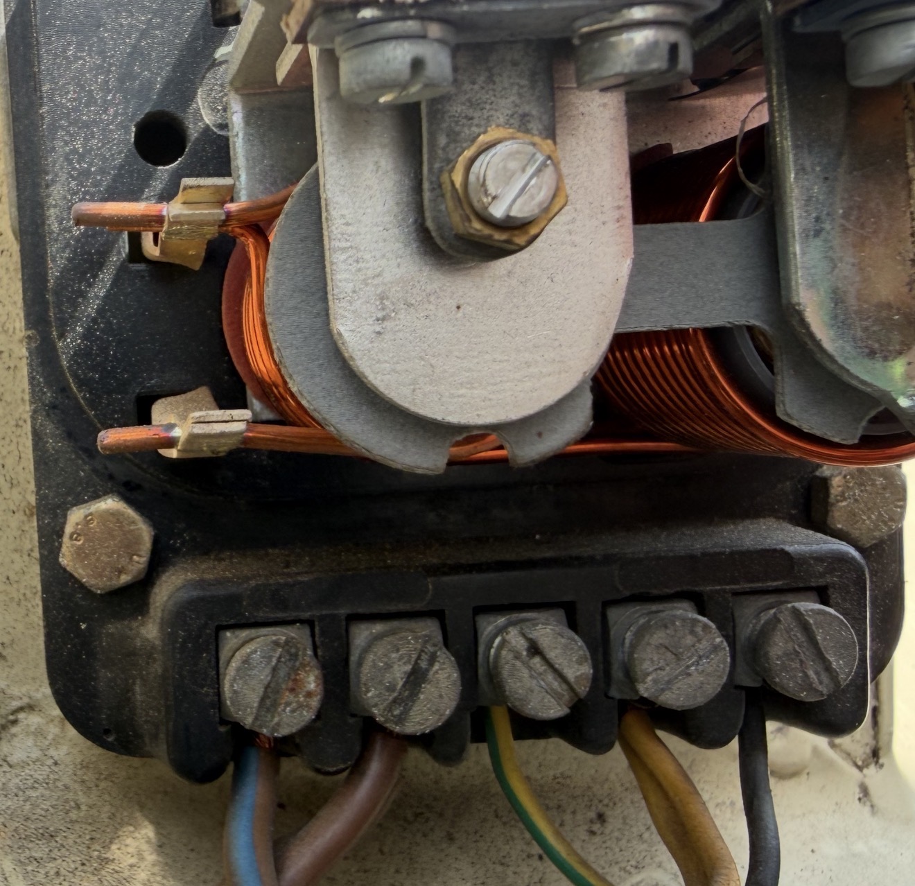
The RB106/2 is a two-bobbin box with exactly two adjustable devices, each with its own sprung brass screw on the frame:
- the voltage regulator, the left-hand bobbin, viewed from the terminal side, which caps how hard the dynamo charges; this is the one that cures overcharging.
- the cut-out, the right-hand bobbin, which connects and disconnects the dynamo from the battery at the right moments.
There is no current regulator on this box: that is the three-bobbin RB310/RB340, a different unit entirely. So you have only two electrical settings to make, the regulator voltage and the cut-out cut-in.
Mind the difference between the two kinds of screw you'll see. The sprung brass adjusting screws are the *electrical* settings this guide uses. The plain armature-securing screws set the mechanical *air gap*, a separate, rarely-needed job covered near the end. Don't confuse them.
Why it must be set on open circuit
This is the crux, and the bit almost everyone gets wrong. The current a dynamo pushes out depends on how flat the battery is, a lot when it's low, little when it's full. Try to set the regulator with the battery connected and the reading is a moving target that reflects the battery's state of charge, not the regulator's true setting. So Lucas set these boxes on open circuit, battery isolated, where the regulated voltage is stable and repeatable.
Two ways to isolate the battery, either is fine:
- slip a piece of dry card between the cut-out contacts (the right-hand bobbin's points), so the dynamo can never connect to the battery; or
- pull the cables off the A and A1 terminals and join them together temporarily.
Everything below assumes the battery is isolated one of these ways. And note the figure this produces: on open circuit the regulated voltage is around 16 volts, higher than the ~14–15 V you see at the battery when the car is running normally. That is correct and expected. Do not "correct" it down towards 14.
What you'll need
- A multimeter set to DC volts, 20 V range (the classic method used a moving-coil 0–20 V voltmeter; a modern digital meter is perfectly good for these readings).
- A small screwdriver for the sprung adjusting screws.
- A piece of dry card.
- A way to hold a steady fast idle (around 3,000 dynamo rev/min), a helper on the throttle, or a hand throttle if fitted.
- A rough idea of the ambient temperature, the target voltage depends on it (see the table).
- Your car is positive earth: the earthed meter lead goes to the + / chassis side. On a digital meter, reversed probes just show a minus sign, read the number.
Step 1, Prepare
- Engine off, battery isolator off. Remove the control box cover.
- Isolate the battery: dry card between the cut-out contacts (or A + A1 removed and joined).
- Connect the voltmeter: one lead to the D terminal (or the bare metal frame of the regulator), the other to a good earth.
- Have your helper ready on the throttle. Work in one smooth pass, because the regulator coil self-heats and its setting drifts as it warms, that bimetal drift is the temperature compensation doing its job, but it means the *meaningful* reading is one taken promptly at a known temperature.
Step 2, Set the voltage regulator
- Start the engine and raise it to a fast idle (~3,000 dynamo rev/min). The voltage should rise, then hold steady at the regulated figure.
- Compare that steady figure with the temperature-corrected target:
| Ambient temperature | Correct open-circuit setting (12 V) |
|---|---|
| 10°C (50°F) | 16.0 – 16.5 V |
| 20°C (68°F) | 16.0 – 16.5 V |
| 30°C (86°F) | 15.5 – 16.0 V |
| 40°C (104°F) | 15.5 – 16.0 V |
As a rule of thumb, subtract about 0.2 V for every 10°C above 20°C, and add the same for every 10°C below.
- If it's outside the band, turn the voltage-regulator sprung screw: clockwise to raise, anticlockwise to lower. Move it a fraction of a turn at a time.
- Re-read from zero each time: drop back to idle, then raise the speed again and read the settled figure. Don't creep up on it while turning the screw, the number only means something once it settles at speed.
- Read promptly: the figure drifts down slightly as the coil warms, so trust the reading taken soon after you reach speed, at your known ambient temperature.
- When it holds within the temperature-corrected band, the regulator is set.
Step 3, Set the cut-out
Now the cut-out (right-hand bobbin), which decides *when* the dynamo connects to the battery:
- Remove the card from the cut-out contacts (or reconnect A/A1 if you used that method).
- Keep the voltmeter on the D terminal (or frame) to earth.
- Start the engine and slowly raise the speed, watching the meter. The reading rises, then dips slightly at the instant the cut-out closes, that dip marks the cut-in voltage.
- The cut-out should close between 12.7 and 13.3 volts.
- If it's outside that, turn the cut-out's own sprung screw, in to raise, out to lower, and re-test from zero speed until it cuts in within range.
Both electrical settings are now made.
Step 4, Final check, on the car
Refit the cover and confirm it all behaves with the battery back in circuit:
- At a fast idle with the headlamps on, the voltage at the battery should settle and hold in the mid-13s to about 15 V, the normal on-car figure, and the ammeter should show a charge that tapers as the battery recovers.
- It should not climb past ~15.5, sit at 16, or spike to 17 at the battery, that would be the overcharge fault you set out to cure.
For the simple on-car voltage check across the battery (dial settings and all), see the companion article linked below.
The mechanical air gap (advanced, only if you've disturbed the armature)
The steps above are the electrical settings and are all most cars ever need. If the box still won't hold a sensible figure, or you've had the armature off, the mechanical air gap between armature and core may need resetting. On the RB106/2:
- Slacken the fixed-contact screw and unlock the armature securing screws.
- Insert the correct feeler gauge between armature and core face. The figure depends on your core type, a square copper separator and a round one take different gauges (typically of the order of 0.38–0.53 mm), so take the exact figure for your box from the Workshop Manual rather than guessing.
- Press the armature squarely down onto the gauge and re-tighten the securing screws.
- With the gauge still in place, screw the fixed contact down until it *just* touches the moving contact, then tighten the lock nut.
- Re-do the electrical voltage setting (Step 2) afterwards, moving the air gap shifts it.
This is fiddly and easy to get wrong. In doubt, leave the air gap alone or hand it to a specialist.
When to stop and fit solid-state instead
Be honest with the box. If, after cleaning the contacts and the earth and setting it carefully, it still won't hold a steady figure, it drifts, spikes, or needs constant fiddling, the electromechanical unit is simply worn out, and no amount of adjustment makes a tired regulator reliable. The sensible, widely-used answer then is a solid-state regulator that hides inside the original box: it holds a rock-steady voltage, ends the overcharging worry for good, and looks original from outside. Remember it is polarity-sensitive (unlike the mechanical box), so order the correct one for a positive-earth car. For a step-by-step of the swap, see Fitting a Solid-State Regulator Inside the Lucas Control Box.
And a caution from experience: those adjusting screws *are* the calibration, so the moment you turn one, you've changed the setting, always re-check the voltage afterwards rather than assuming a "small nudge" did no harm.
Related reading
- The Lucas Control Box: how it works and how to fault-find it → /technical-library/lucas-voltage-regulator-control-box. Start here for what the box does, the terminal diagram, and the overcharging fault-finding order.
- From the Workshop: a TF1500 Health-Check → /technical-library/workshop-tf1500-overcharging-rich-running. A real overcharging diagnosis on a T-Type.
*These are the published Lucas settings for the RB106/2, a guide, not a substitute for the official MG Workshop Manual. Confirm the model stamped on your own box, and if you are not confident working near a running engine with live terminals, entrust the job to an auto-electrician.*